I accept VadaTech copyright information.
Home
Products
Newsroom
By Function


 |
I accept VadaTech copyright information.
Please enter your email registered at VadaTech and we will send you your password.
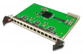
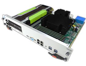
At the heart of any AdvancedTCA (ATCA) or MicroTCA (uTCA) system is the switch. This is usually implemented as a blade in ATCA systems or as part of the MicroTCA Carrier Hub (MCH).
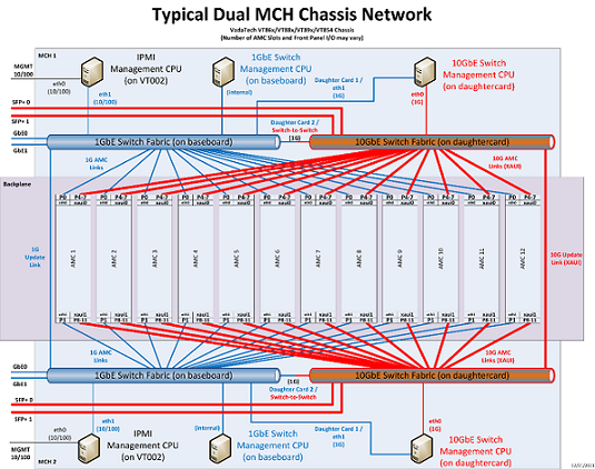
In a uTCA system, the MCHs in the chassis not only connect to the AdvancedMC (AMC) payload modules but also connect to each other (update links), and 1G and 10G switches are also cross-linked (switch-to-switch links).
RSTP runs by default on both the 1G and 10G switches in order to ensure that the network graph of forwarding ports has only a single path from any node to another (loop-free). RSTP also makes use of redundant links to provide improved fault-tolerance; if one of the links in the active graph goes down RSTP will enable one of the redundant links.
Decisions on architecture should be driven by the needs of your application and, when it comes to switching choices, bandwidth and redundancy/failover are critical criteria. Both ATCA and uTCA systems support redundancy, fail-safe operation and hot-swap, but the implementation caries widely across the two technologies and various manufacturers’ products.
Some applications may require that the 10G network be considered the ‘data plane’ while the 1G network be considered the ‘control plane’. In these applications it is frequently desired that the two networks not be able to forward into each other.
Similarly, some applications may require that the MCH1 networks be kept separate from the MCH2 networks. VadaTech has developed flexible solutions to address all these requirements and can support you in tailoring our products to suit your application.
Our datasheets and user manuals provide more information on the options available and how to access and enable them. For more information, please contact one of our technical experts.
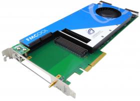
PCI Express was introduced to overcome the challenges of the PCI bus and is specified in layers. The software layers generate read and write requests that are transported by the transaction layer to the I/O devices using a packet-based, split-transaction protocol. The link layer adds sequence numbers and CRC to these packets to create a highly reliable data transfer mechanism. The basic physical layer consists of a dual simplex channel implemented as a transmit pair and a receive pair. The transmit and receive pair together are called a lane.
VadaTech has implemented a sequenced power-up to ensure that root complex and endpoints activate or deactivate in the right order.
Additionally, VadaTech has published a white paper on separating digital acquisition and processing from local computing via PCIe expansion.
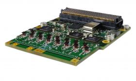
The basic concept of the crossbar switch is the ability to route any SERDES output (Y) from any SERDES input (A). This means that any output can re-drive any single input, while any input can route to zero or more outputs. This configuration allows for flexible point-to-point or point-to-multipoint configurations.
This type of switch operates in a circuit-switched fashion instead of a packet-switched fashion as would be typical of an Ethernet switch. This means that circuits are set up ahead of time to form paths through the switch and they will not change based on the content of the traffic flowing through the switch.
The crossbar switch can be visualized as follows:
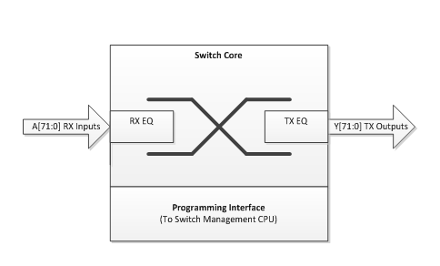
This fabric can support various types of communication standards such as SATA, SFI-5, TFI-5, ATCA, PCIe, XAUI and InfiniBand. The switch fabric itself does not need to understand the protocols flowing through it, it simply re-drives the SERDES line states. It is the communicating nodes themselves which must understand the protocols.
Serial RapidIO (SRIO) is a high-performance interconnect technology used to connect multiple processors, FPGAs, or DSPs together in a system. Optimized for low latency, SRIO is widely used in communications and embedded and industrial systems. VadaTech supports SRIO technology in many chassis, MCHs and processor AMCs.